The design parameters which affect the. Biomass gasification in a bubbling fluidized bed reactor Oct 10 2006 A model is presented for the gasification of beech wood particles in a bubbling fluidized bed gasifier BF Tel.

Process Schematic For Bubbling Fluidized Bed Download Scientific Diagram
A typical fluidized bed reactor.
. Equipment Design The movie below shows the operation of a fluidized bed reactor. Circulating fluidized bed reactor design and operation 39 --favourable turndown typically 41 and good load following capabilities. Powder Technology 72851973 191331978.
Abstract A fluidized-bed reactor was designed and constructed for practical demonstration of the fluidization of solid particles at different fluid flow rates. Two dimensional bed of 1m height and 028 width is taken. We are going to use the Kunii-Levenspiel bubbling bed model to describe reactions in fluidized beds.
The disadvantages of fluidized beds are summarized below. Principle Fluid Passes through Bottom with low velocity first to settle down the Solid Material on the Porous Plate called Distributor. A laboratory scale fluidized bed reactor was designed and fabricated successfully.
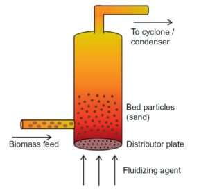
Download Citation Bubbling fluidized bed biomass gasification using a two-stage process at 600 C. Types Of reactor 1Bubbling Fluidized Bed 2Circulating Fluidized Bed 3Flash Reactor 4Annular Fluidized Bed 3. Typically the process consists of a vertical cylindrical tube with a perforated distributor plate at the lowest.
Scaleup of fluidized beds can be difficult 1. In Brownsville Texas in 1950 two large 5-m-diameter bubbling fluidized bed FischerTropsch reactors were built based on the results from a 03-m-diameter pilot plant operated with a Group B iron catalyst. Ring Fluidization Minimum Fluidization Void Fraction Superficial Velocity Bubbling Bed Expansion Prevent Slugging Poor gassolid contact Fluidization Fluid Bed Particles mean particle size Angular Shape Factor Void fraction 04 bulk density Geldart D.
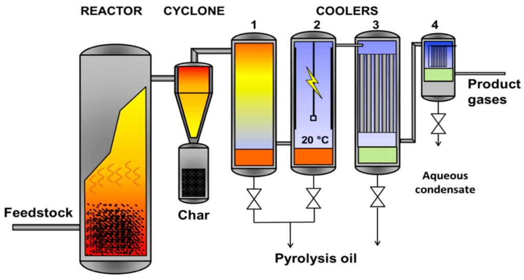
This paper describes a pilot plant scale circulating fluidized bed unit recently designed constructed and put into operation in the Pulp and Paper Centre at the. Bubbling beds of fine particles are difficult to predict and are less efficient Rapid mixing of solids causes non-uniform residence times for continuous flow reactors Particle comminuting breakup is common Pipe and vessel walls erode due to collisions by particles. Consequently the proposed design of the bubbling fluidized bed gasifier for EFB briquette gasification will consist of three main parts.
51 cm diameter bubbling fluidized bed reactor FBR fed with milled pine pellets. The fluidized bed gasifier FBG is considered the most suitable reactor for biomass gasification due excellent mixing efficient heat temperature control and tolerance for fuels. Fine particle fluidization the FCC process was proposed was chosen commercial plants were built.
Fluidized beds typically are more complex to design build and operate than other types of reactors such as packed-bed and stirred-tank reactors. Modeling the Bubbling Fluidized Bed Reactor BFB. The reactor consists of three sections.
The bed of this reactor was sand particles of average size 1800 μm weighed 06 N and the fluidizing fluidwas air. DESIGN AND CONSTRUCTION OF A FLUIDIZED BED by Robert Ryan Mota Bachelor of Science California State Polytechnic University Pomona 2010 A Thesis. Fluid Bed Reactors Chapter Not in book CH EN 4393 Terry A.
Bubbling Fluidization This type of fluidization has been called aggregative fluidization and under these conditions the bed appears to be divided into two phases the bubble phase and the emulsion phase. The yields from the larger units were found to be disastrously less than those obtained in the pilot plant unit. A bed section b freeboard section and c conical closure section with inlet cone.
When this begins to happen the bubbling and agitation of the solids are still present and this is known as the region of fast fluidization and the bed is a fast-fluidized bed. Numerical study of the hydrodynamics of a freely bubbling fluidized bed is studied here. As the bubbles rise mass transfer of the reactant gases takes place as they flow diffuse in and out of the.
To intense the solids movement in the fluidized bed a conical tube. Before the reactor is started the catalyst pellets lie on a grate at the bottom of the reactor. Feeding gasification and and the cost of fabricating porous plate distributors.
Fluidized beds are prone to erosion and particle attrition caused. Fluid passes through the voids of the solid material. It was made out of plexiglass and in the centre an injector lance with a length of 482 mm was installed.
The pyrolysis of biomass starts in the bed reactor thanks to the high thermal exchange with the oxidant agent. Correlations and models for the prediction of the minimum fluidization and bubbling conditions the expansion and voidage of fluidized beds the size and velocity of gas bubbles are thus presented. Reactants are pumped into the reactor through a distributor continuously causing the bed to become fluidized.
At velocities beyond this region the particles are well apart and the. BUBBLING FLUIDIZED BED REACTOR Published June 9 2019 Updated July 21 2019 A fluidized bed consists of a bed of particles thats unbroken fluidized by the continual upward flow of a gas. The fluidized bed reactor model had an inner diameter of 190 mm and a height of 2000 mm.
Part B presents a synthesis of the literature available on selected subjects of primary importance to the design of fluidized bed reactors. A way to avoid bed agglomeration Air gasification of wood pellet was conducted using a. The predicted FBR hydrodynamics included estimates of the residence times that the gas and biomass particles spend in the reactor before they exit.
Bubbling Fluidized Bed Reactor 4. Feeding zone gasification. Some material in particulate type.
The experimental pyrolyzer consisted of a 2 in. The beds behavior after initial fluidization depends on. This is due The proposed bubbling fluidized gasifier system for EFB to the simplicity of the design minimal operating constraints briquette consists of three main parts.
In this model the reactant gas enters the bottom of the bed and flows up the reactor in the form of bubbles. Bubbling fluidized beds are composed by a grid air-distribution at the bottom of the reactor to allow a good uniformity of the oxidant agent in the biomass particles avoiding thermal gradients along the radius of the reactor. Octave Levenspiel Emeritus Professor Oregon State University During the Second World War the US had an urgent need to produce enormous quantities of aviation gasoline.
Eventually if the gas velocity is increased continuously it will eventually become sufficiently rapid to carry the solid particles upward out of the bed. The bubbles appear to be very similar to gas bubbles formed in. The nozzle on top of the lance had an outlet diameter of 10 mm.

Bubbling Fluidized Bed Reactor With An Electrostatic Precipitator Download Scientific Diagram

Bubbling Fluidized Bed An Overview Sciencedirect Topics
Bubbling Fluidized Bed Reactor Chemical Engineering World

Fluidized Bed Reactor Wikipedia
Bubbling Fluidized Bed Reactor Chemical Engineering World

Schematic Diagram Of A Bubbling Fluidized Bed Reactor Download Scientific Diagram

Bubbling Fluidized Bed Reactor 76 Download Scientific Diagram

Characteristics Of Fluidized Bed Reactor Download Scientific Diagram
0 comments
Post a Comment